Simple 3-Column Index
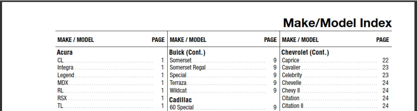
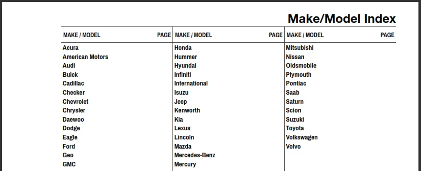
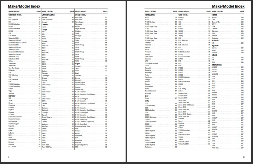
This tutorial will take you through the steps necessary to produce a simple 3-column index as shown below:
- In preparation for this tutorial, download the attached zip file (at the bottom of this page) and save it to your desktop. Open the zip file and extract the contents to a new directory called “SimpleIndex” under your “AcePrint Projects” folder. Normally:
C:\Users\<yourname>\Documents\AcePrint Projects
-
File > New. To create a new catalog. Name it “MySimpleIndex” and save it to the SimpleIndex folder above.
-
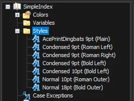
Click on “Styles” and Right-Click to Add Style. Add a new style for each of the styles shown below. For the Condensed font, select “Archivo Narrow”. For the Normal font, select “Arial”. (Plain / Roman means no style check boxes. Bold means the Bold check box is selected.) Select “Use Kerning” for all, and point Size and Alignment as indicated in the style name.
-
Click on “Sections” and Right-Click to Add a Section. This will create an empty section. Name it “Make/Model Index” with Margin values (1p6, 7p3, 1p6, 2p9). Check “Use Roman numeral page numbers” and Select the “Lower case” option.
-
Click on “Make/Model Index” section and Right-Click to Add a Layer Group. This will make an empty layer group to hold our static page header. Name it “Page Header” and set its Location Relative to “Margin - Top Left”. We don’t strictly need a Layer Group here since it will only contain one element, but it is a good practice in any case.
-
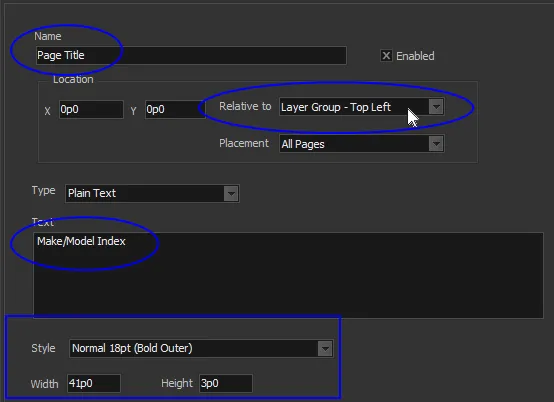
Click on “Page Header” layer group and Right-Click to Add a TextBox. This will create an empty text box to hold the page title. Name it “Page Title” and set its Location Relative to “Layer Group - Top Left”. Enter “Make/Model Index” for the Text, “Normal 18pt (Bold Outer)” for the Style and Width 41p0, Height 3p0.
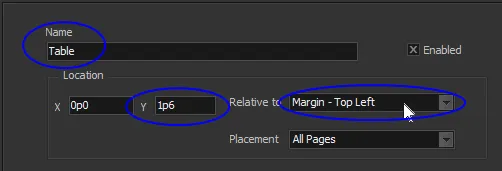
- Click on “Make/Model Index” section and Right-Click to Add Table. This will create an empty table element for formatting external data. Name it “Table” and set the starting Location to 0p0, 1p6 Relative to “Margin - Top Left” (so we don’t overprint the Page Title).
Next we want to tell the Table where to get the external data and what type of file it is (we support delimited text files and Access databases). In this case, our source file is a tab delimited text file with no text delimiter. (Excel exports will always include double quote Text delimiters).
- Press the Source File […] on that same page. This will bring up a Windows File Open dialog. Select “MakeModel_Index.txt” from the SimpleIndex folder you created in step 1. Select “Tab Delimited”, “Has Field names” and Text Delimiter “{none}” as shown below.
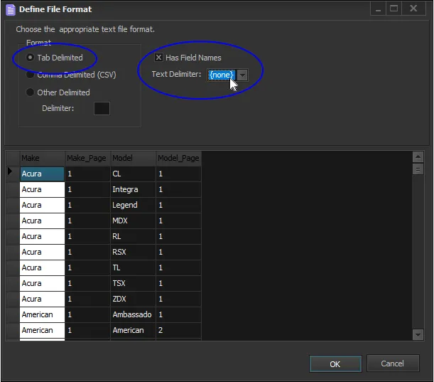
This source file was actually created by AcePrint using the Indexing feature, but we will cover that topic in a future tutorial.
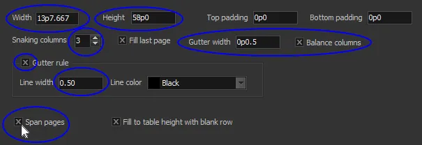
- Fill in the table Width, Height, number of columns, gutter width (amount between columns) and allow a 0.5pt rule between columns (in the gutter). Finally be certain to check “Span pages” (since every section with a table that may be more than one page must have that one table defined as spanning).
You might ask how we came up with a width of 13p7.667? Here is the calculation (also included in Sizes.xlsx in the attached zip file).
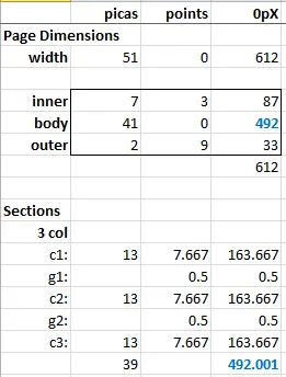
After subtracting the inner/outer margins from the paper width of 8.5” (51p0), we have 41p0 (492 points) to work with. That needs to be divided up into three columns and two 0.5pt gutters. The math works out to 13p7.667 per column (although not perfectly since we are one thousandths of a point off!).
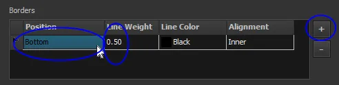
- Press the Plus Sign (+) and add a “Top/Bottom” Table Border. Set the Line Weight to “.5” points.
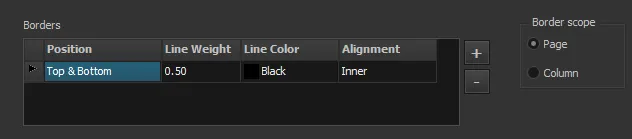
This will put a border above and below the entire table (defined by its Height of 58p0). If we had selected “Column” for the “Border scope”, it would not include the gutters.
Now we want to handle the way headings are continued from one column to the next. These are sometimes called “jump heads”, “repeating heads” or “continued heads”.
- Select Make from the Available list and Press the Left Arrow. This will create a row in the grid with that field in the “Group By” column. Enter “%s (Cont.)” in the Continue column.
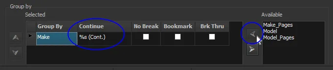
Anything found in this “Group by” grid can be used as a Group Head. These heads can repeat at the top of a new column (or page), and if they do, they will use the pattern included in this “Continue” column. The “%s” is a placeholder for the actual group value (the Make name in this case).
These “Group by” fields also control the drawing of “Top” borders at the cell level. We will see this feature being used in a future tutorial.
Now let’s create the static table headings (“MAKE / MODEL” and “PAGE”) that always repeat at the top of each column.
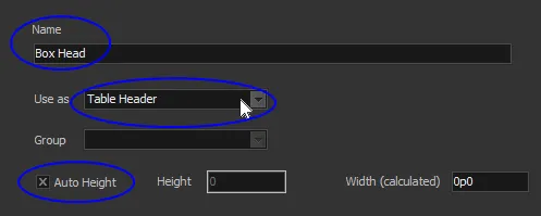
- Click on the Table “Headers” container and Right-Click Add. This will create a new header. Name it “Box Head” and Use as “Table Header”. Select “Auto Height” to indicate that it will take its height from the total of its sub-elements.
This only creates the container. Now we need to give it some static text. The best way to position static text in a table is with the Layout cell. (Although we could have also placed Static Textboxes directly under the head container, in which case they would have a width and be laid down right next to each other across the page).
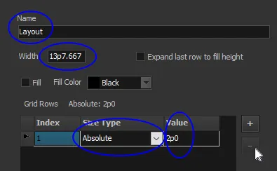
- Click on “Box Head” and Right-Click to Add a “Layout cell”. Change the Name to “Layout” and set the Width to “13p7.667”. A new layout cell defaults to two rows and two columns. We need to remove one of the rows (press the minus sign [-]), and change the Size Type on the remaining row to “Absolute” with a Value of “2p0” for the row height. This is so we let the heading breath some.
- Set the Grid Columns to the Layout as follows:
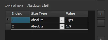
Note that we didn’t make the columns add up to exactly 13p7.667 (a running total is shown above the grid: 13p6 in this case). We could have made them match, but we wanted to show that the borders are drawn using the Layout “Width” value. Not the total column value. In this case our second column will have a 1.667pt right padding.
- Add a Bottom Border to the Box Head Layout as follows:
Now, let’s add the static text boxes to our layout, one for each column in the table.
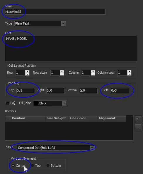
- Click on “Layout” and Right-Click to Add a TextBox cell. The Cell Layout Position “Column” for this text box is already set to use the first column in the layout, so we can leave this alone.
The effect we want is for the heads to center within the 2p0 row height we provided in the layout. We do this by selecting the “Center” Vertical Alignment. But because we are using upper case titles, we want to move it down a bit more. To do this, add a 0p2 Top Padding. (We could have just as well left the “Top” Alignment and made a 7pt Top Padding to get a similar effect).
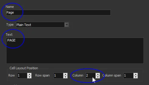
16.Click on “Layout” and Right-Click to Add a second TextBox cell. Fill in the values as above and shown below. The main difference is that you need to select “2” in the Cell Layout Position “Column”.
Let’s now add the heading that will be printed whenever a new Make is found in the data. Since we already set Make as a Group by column, it will be available as a group head.
- Click on the Table “Headers” container and Right-Click Add. This will create a new header. Name it “Make Head” and Use as “Group Header”. Select the “Make” column as the Group and Select “Auto Height”.
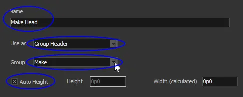
This makes a header container that will be used whenever a new Make is found. Auto Height means that it will take on the height of whatever elements are included in the container.
Now we’ll introduce a new type of text box that takes its value from the data file instead of from static text provided in the screens. It is called a “text data cell”.
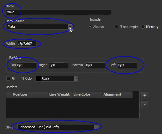
- Click on the “Make Head” container and Right-Click Add a “Text data cell”. Change the Name to “Make”, the Data Column drop-down to “Make” (indicating which field from the data file to use), and the Width to the table width 13p7.667. Note that we also set some padding for this text element. Generally, a left padding of 2 or 3 points looks good when you have a border. The heading uses a bold font.
At this point, if we generated the PDF, it would look something like the following:
This is just what we would expect. We have our Page Title, our Box Heads, our snaking table with gutter rules (borders) and a list of Makes found in the data file. Notice also that the columns are balanced (using the same number of rows) as best it could.
Now let’s add our models and page number data. We would normally use another Layout cell for flexibility, but in this case we will just add the data cells directly to the Data Row container.
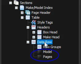
- Click on the Table “Data Row” container and Right-Click Add a “Text data cell”. Name it “Model” and select “Model” for the Data Column to pull the data from. Give it a Width of 12p0 and 3pts of Left padding.
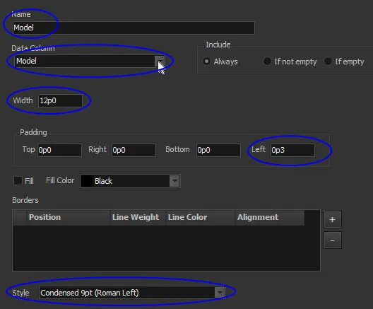
The Width is very important because it determines the bounding box for the current field, but also where the next data element will start (i.e. they are placed right next to one another).
Note that the Data Row container defaults to “Auto adjust height” which means it takes its height from the total of its sub-element’s heights. In this case that height is determined by the point size (9pt).
Next we want to add “leader dots” to help the eye move from a model to its associated page number. Further down on the same page is a setting for this feature.
- Select “Dot Leaders” check box. And select the “AcePrintDingbats” style. We could have used the same style as the Model, and a period (”.”) for the leader dot Character, but that would produce a fairly heavy leader. This is why we provide special leader dot characters in the AcePrintDingbats font.
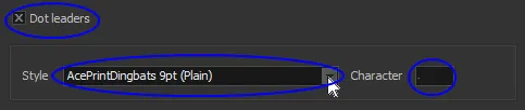
The Character looks like a period in the above screen shot, but it is actually a special dot leader character. We provide two separate characters for this purpose in the AcePrintDingbat font. You can experiment with the double dot leader which will create a more compressed line of dots. The easiest way to enter one of them is with the Windows “Character Map” application:
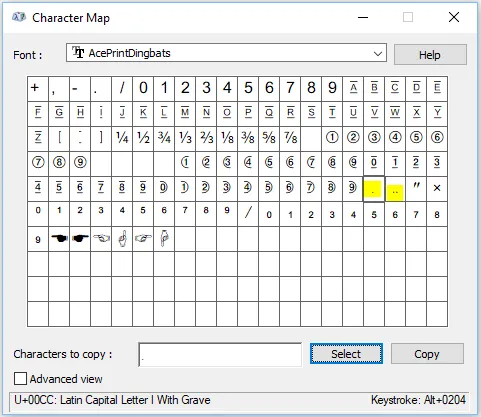
Select the single dot that is highlighed above (or take it from this character below):
Ì
Press the Copy button (or Ctrl-C) and past (Ctrl-V) into the Character field in AcePrint.
Now let’s add the second data column for page number:
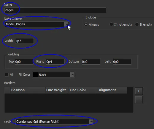
- Click on the Table “Data Row” container and Right-Click Add a “Text data cell”. Name it “Pages” and select “Model_Pages” for the Data Column to pull the data from. Give it a Width of 1p7 and a right aligned font Style. Note that we also add a 4pt Padding on the right. This will keep it from being too close to the gutter lines.
Finally, let’s put a page number at the bottom of the page.
- Click on the section “Make/Model Index” and Right-Click Add TextBox. Change the information to match the below.
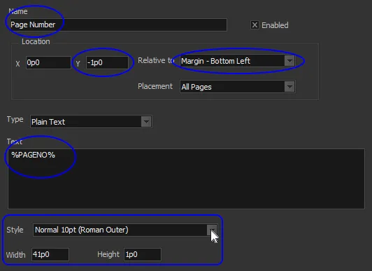
Note that we made this text box relative to the bottom of the page. So we included a negative Y value equal to the Height of the box.
Also, since we used the full 41p0 measure for the Width and a Style with Outer alignment, the page numbers switch back and forth nicely from the left side to the right.
If you now press the “Create PDF” button, you will see several pages of a nicely formatted index:
Tutorial_SimpleIndex.zip (800 KB)